
Unity Depth Camera Simulation
Simulated Depth Camera Images
In this tutorial, we’re going to create synthetic RGBD images with the Unity game engine. RGBD stands for Red Green Blue Depth, and typically is saved as two separate images. One containing the original image, and another showing depth in greyscale or using a color gradient.

The RGB image we’ll be making in this tutorial

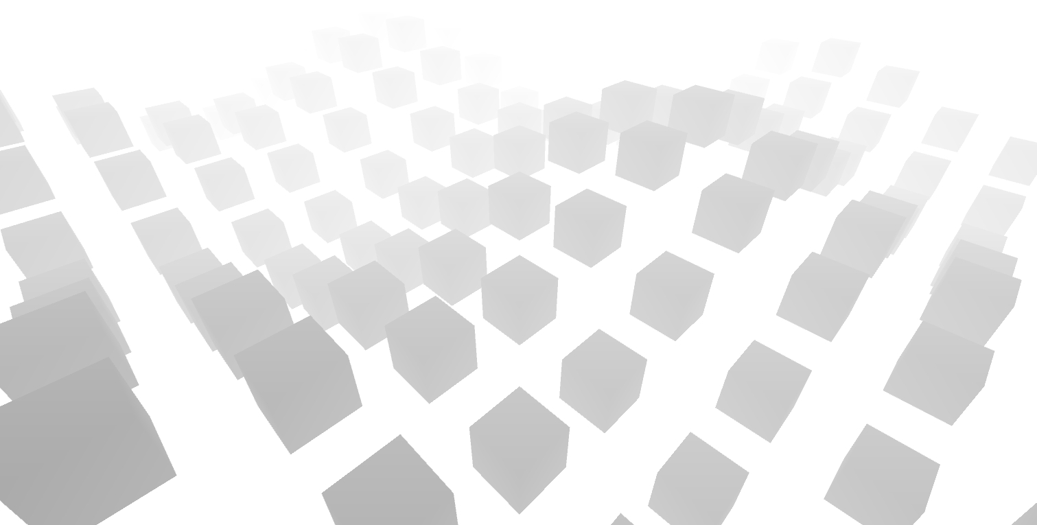
The Depth image we’ll be making in this tutorial
Rather than reinvent the wheel, I’ve modified code from Unity’s ML-ImageSynthesis project to render depth images.
Get the GitHub Repo
A sample Unity project repository can be found here: https://github.com/immersive-limit/Unity-ComputerVisionSim
Open the Unity Project
The Sample Scene has only three objects in it. A Main Camera, with an ImageSynthesis script attached, a Directional Light, and a CubeField, with a CubeField script attached.
Press Play
Things get more interesting! You should see what I decided to call a “cube field” animating along the Y-axis via sine waves on X and Z. This is simply for us to visualize something interesting.

A sine wave animated field of cubes that will appear when you press Play.
Change to Display 4
If you change the display in the Game window to “Display 4” it will show your depth image.
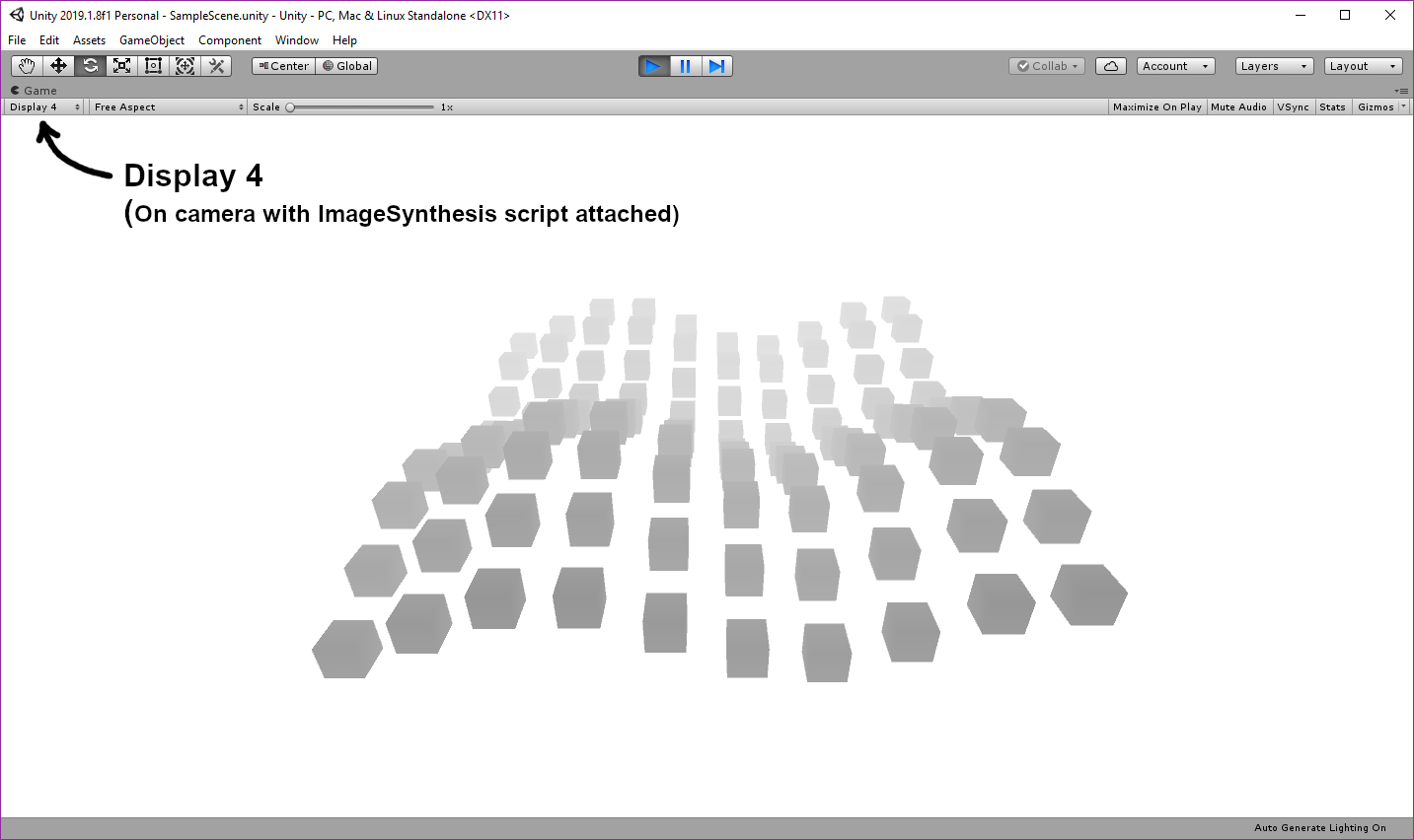
Simulated depth camera image in Unity
Check Out the Camera
Clipping Planes
The only thing I’ve changed on this camera is the Clipping Planes. If your clipping planes are set to default values of .3 and 1000, your depth map will be black at .3 meters and white at 1000 meters and beyond. Imagine stretching out a gradient over 1 kilometer and you’ll see why this isn’t ideal for us. A real depth sensor has a range of about 10 meters and it doesn’t work very well up close. You can choose to simulate your actual ranges for your project, but for this example, a Near plane of 5m and Far plane of 20m fits the cube field nicely.

Image Synthesis - Inspector Setup
I’ve made a few additions to the original Image Synthesis script.
A list of checkboxes that allow you to choose which image captures you want to save. (Optical Flow doesn’t work yet)
Filepath - If you leave this empty, the captures will save to your Unity project directory (next to the Assets folder).
Filename - The code will take your filename and insert the capture pass name for each pass, (e.g. test_img.png, test_depth.png)

When you press play, a “Save Captures” button will appear. This will save your selected captures to your filepath.

When you press “Save Captures”, it will save all checked captures to the filepath you specified (relative to the Unity project folder). You will notice some other captures in here, but we’re only interested in test_depth.png for now. I’ll post more about the other images in another tutorial.

All five captures saved in the Captures directory.
Image Synthetsis
ImageSynthesis.cs contains the logic for setting up all camera capture passes. Here’s the high level overview of how it works:
It creates a list of CapturePass structs containing basic info about each pass (e.g. “_img”, “_depth”)
In Start(), it assigns the camera to capturePasses[0], then creates a hidden camera for the remaining capturePasses
In OnCameraChange(), it copies settings from the main camera and assigns a target display for each hidden camera
It calls SetupCameraWithReplacementShader() for each hidden camera to tell the shader what type of _OutputMode to use
In OnSceneChange(), it does work for object segmentation, which I’ll explain in another tutorial
In Save(), it does the work to save each of the capture passes to the specified directory
Uber Replacement Shader
UberReplacement.shader is where the rendering magic happens. The shader is pretty long, but we really only need to understand part of the first SubShader.
The vert() function computes the depth and passes it to frag()
The frag() function passes that depth info to Output() and returns the value
Look at the Output() function’s DepthCompressed section ( _OutputMode == 2), where you will see the depth calculated using the Near clipping plane and Far clipping distance.
This depth calculation is returned for each vertex in the image (via the frag() function)
If shaders aren’t your strong suit, here are a couple excellent resources to bring you up to speed:
Shaders 101 - Intro to Shaders: https://www.youtube.com/watch?v=T-HXmQAMhG0
Shaders 102 - Basics of Image Effects: https://www.youtube.com/watch?v=kpBnIAPtsj8
Shaders 103 - Using Replacement Shaders: https://www.youtube.com/watch?v=Tjl8jP5Nuvc
Catlike Coding - Shader Fundamentals: https://catlikecoding.com/unity/tutorials/rendering/part-2/
Image Saver
This is a simple script that adds an image capture button to the inspector window for ImageSynthesis when in play mode. It’s more intended as a guide than as something I’d expect you to use in your own project. You’d probably want to automate saving images.
Conclusion
Here’s our output image from the depth pass. Hopefully this tutorial gave you a good idea of how to get depth working in Unity. In a future tutorial, I plan to use this depth data to train a neural network on RGBD images.
